EMC Measurement: Basics
Bus modules are generally designed and built to withstand all types of external electromagnetic interference. Certificates by EMC laboratories (EMC = electromagnetic compatibility) are the basis for any product certification.
Regardless of all the testing, sporadic failures of bus systems occur again and again for no obvious reason. Replacements at the visible fault locations (red error LED) might restore the apparent functionality of the system. However, over the last 10 years, suppliers and operators of fieldbus systems have come to realize that, in most cases, the visible fault location ”red error LED“ has nothing to do with the real cause of the problem. The conclusions drawn from this insight – often after a protracted process accompanied by painful losses and failures – can be summed up by ”troubleshooting by using diagnostic and service tools“ or ”permanent network monitoring in the sense of condition monitoring“.
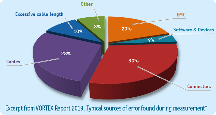
Measurements have confirmed that approx. 40% of bus failures are caused by physical transfer quality issues. In addition to installation errors (becoming less frequent nowadays), such failures are obvious consequences of the production environment. Oxidation and corrosion caused by humidity or aggressive media within the contact points, line rupture caused by excessive alternate bending, or simply ageing of components could be identified by measurements as causes of sporadic failures.
Currently, a new phenomenon has appeared during the search for causes of bus failures. It has been noted that data communication issues are becoming more frequent in situations where the system itself does not reveal any weak points.
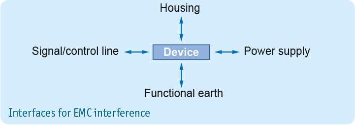
It was the investigation of shield currents on industrial data communication lines that prompted the diagnostic approach to take a completely new turn. It soon became clear that the bus itself was in perfect condition but was being affected by external influences that are generally referred to as ”EMC interference“. Further, extensive measurements, both in the PE/PA system and in the shielding connections of bus lines, revealed an association between high leakage currents (mostly of higher frequency) and bus failures.
The following facts and circumstances are presented for explanation and better understanding of the above statements:
- Equipotential bonding (PA) provides protection against contact, and a signal reference potential (protective bonding and functional bonding).
- Operational loads on the bonding system should be as low as possible.
- In the interest of potential bonding, all connections of earthing points should be not only low-resistance but also low-impedance.
- All bus modules in a network share the same signal reference earth.
- Fieldbus systems require a concept for continuous shielding with the shields connected at both ends at least.
- There must be no voltage differences within the reference potential.
- A multiple earthing of the negative pol (24V DC power supply) influences the network through leakage current. This might cause device failures.
- When integrating fieldbus networks into existing TN-C systems, the equipotential bonding requires particular attention.
New systems are increasingly installed into older or existing buildings. Experience has shown that system suppliers rely on the specifications provided by the operator, or take a functioning equipotential bonding for granted. They neglect to verify or certify the function or resilience of the existing PA.
Definitions
Equipotential bonding (PA)
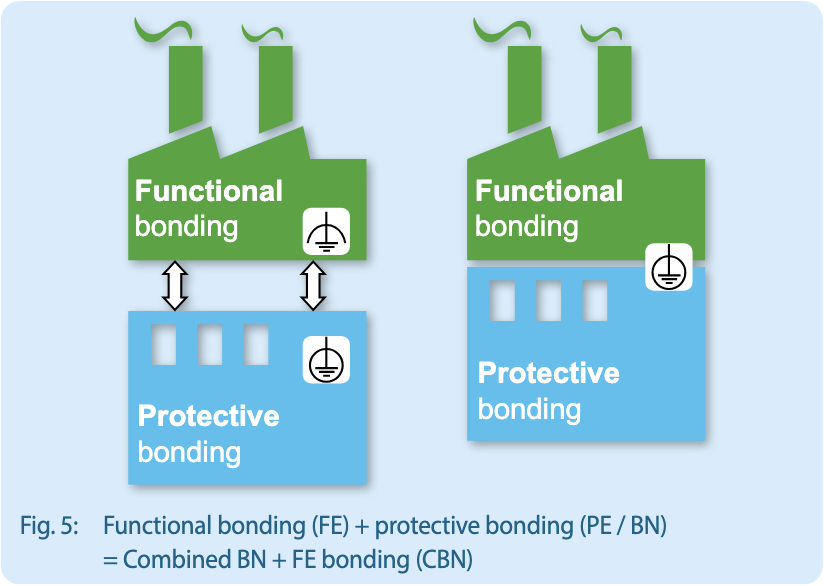
The objectives of equipotential bonding include the protection of people and animals against electric shock as well as electrical functions such as providing a uniform signal reference potential. A distinction is therefore made between protective bonding and functional bonding.
Protective bonding PA or BN (bonding network)
This involves establishing electrical connections between conductive parts in order to equalize potentials for the protection of people and animals. (Important aspects include current carrying capacity and ohmic resistance.) This requires copper with a minimum cross-section of 6 mm² (DIN VDE 0100-540).
Functional bonding / earth FE
This involves establishing a uniform, low-impedance signal reference potential for the electronics.
Protective earth (PE)
Protective earth (PE) protects against excessive body currents and must only carry current in the event of a malfunction.
Functional earth (FE)
Functional earth (FE) has to ensure error-free operation of electrical systems and devices. The functional earth conductor should not be labelled green/yellow.
CBN (common bonding network)
A bonding system that provides protective and functional bonding.
MESH-BN
A meshed equipotential bonding system where all involved conductors are connected to each other and at many points to the CBN.