MULTIrep X2 | PROFIBUS Repeater with Integrated Diagnostics
Networking

ⓘ Please contact us for partner and OEM pricing here.


Long cable runs, high device counts, and segment faults are manageable PROFIBUS problems when your repeater gives you the right information. The MULTIrep X2 PROFIBUS Repeater combines signal regeneration, segment isolation, and built-in LED diagnostics in a single unit, so you can extend your network without losing visibility. Drop-in compatible with Siemens repeaters.
Overview
Using a repeater allows an enlargement of your PROFIBUS network until up to 126 devices and to create higher line lengths depending on the fieldbus transmission speed. Per segment, a maximum of 32 devices (31 + repeater) is acceptable. The MULTIrep produces a voltage signal in two, five or seven directions (depending on the version) and raises the signals to the PROFIBUS standard level.
From the physical point of view the MULTIrep provides up to seven isolated segments. The integrated diagnosis via LED allows for simple troubleshooting in each segment.
This repeater enhances network reliability by isolating sensitive segments and regenerating weak signals to meet PROFIBUS standards. It also supports expansions or maintenance without shutting down the entire network.
Key Benefits
- Drop-in replacement for Siemens diagnostic repeaters
- Basis for a stable PROFIBUS star or stub structure
- Built-in diagnostics via segment LED display
- Errors are isolated to affected segments only
- Enables expansions during running operation
- Up to 7 galvanically isolated segments (X2 supports 2)
- Ideal for star topologies and runtime expansions
Instruction for use
Using the MULTIrep creates up to seven galvanically isolated segments. For the purpose of diagnostic measurements a measuring point should be provided at the beginning and end of every segment. Therefore, the PG interfaces at the 9-pin sub-D plugs can be used as measuring points.
If a segment ends or begins directly at the connections of the repeater, it is necessary to activate the bus terminating resistors at the plugs.
Fieldbus connection and termination
PROFIBUS is connected by a 9 pin sub-D socket (according to PROFIBUS guideline). If the segment ends or starts directly at repeater terminals, bus termination resistors have to be activated directly at the plugs.
Segment Diagnostics via Status LED
- Bus: Status of the fieldbus per channel
- Green: Okay
- Red: Error telegram, telegram repetition, diagnostic message, device failure
- Data:
- Green: Fieldbus activity on the channel
- Red: Configured problems in PROFIBUS
- OFF: No fieldbus activity
Technical Specifications
- Voltage Supply: 24 VDC ±20%
- Power Draw: 0.3 A
- Baud Rate: 9.6 kbps to 12 Mbps
- Connection: 2 x 9-pin Sub-D (X2 version)
General Specifications
- Installation: 35 mm DIN rail
- Dimensions (H x W x D): 105 x 75 x 40 mm
- Protection Class: IP20
- Operating Temp: +5°C to +55°C
- Storage Temp: -20°C to +70°C
- Supported Protocols: PROFIBUS DP, DP-V1, FMS, MPI
MULTIrep: Features and benefits in detail
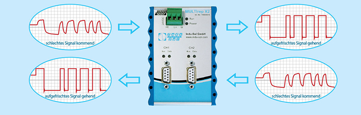
Signal regeneration for trouble-free data communication
With the MULTIrep repeaters, the voltage signal required for data communication is regenerated in both line directions and raised to standard PROFIBUS level. However, the signal content remains unchanged, ensuring smooth data communication in large segments and/or long cable runs.
Stable star structure possible
With the MULTIrep PROFIBUS repeater series, it is possible to divide your network into two, five, or seven galvanically isolated segments, depending on the expansion stage. As a result, local, functional, or technological groups can be formed depending on the purpose. The classic line structure is dissolved. The star-shaped arrangement of many small segments with signal refreshment brings numerous advantages for stable operation and troubleshooting. These are known, among other things, from Ethernet-based networks.
Expert advice: We recommend the use of repeaters to separate conspicuous or interference-prone participants. The galvanic separation of the segments prevents effects on the complete PROFIBUS system.

Classic line structure example

Star structure example with the MULTIrep X5
Integrated quick diagnosis and error filtering
All repeaters of the MULTIrep series permanently monitor the PROFIBUS telegram traffic. The status LED on the device signals any occurring logical or physical anomalies. Error telegrams and telegram repetitions are also signaled by the bus LED. The data LED generally indicates whether the slaves on the channel are communicating and if there are any configuration errors. Therefore, the health status of the respective PROFIBUS segment can be permanently monitored and checked quickly.
The integrated diagnosis enables the maintenance technician to narrow down the error to the affected segment. The status LED makes this segment easily identifiable.

If error telegrams or signal interference occur in a segment with repeaters, errors are automatically filtered and not transferred to other segments, preventing interactions outside the affected segment.


, and the leakage current clamp, LSMZ I (12201005)")


